Introduction
Design pressure defines the structural limits of an atmospheric storage tank — and it's frequently misunderstood. The term "atmospheric" leads many operators to assume these tanks operate at zero pressure, but they experience continuous pressure fluctuations above and below ambient during normal breathing cycles. That misunderstanding has contributed to real-world failures, including catastrophic vacuum collapses and roof separations.
This guide covers how design pressure is defined under API 650 and related standards, which numerical ranges apply, how tank configuration and venting devices drive the final value, and what consequences follow when those limits are breached.
Key Takeaways
- Design pressure is the maximum internal and external vacuum pressure a tank is engineered to safely withstand, always set above operating pressure to provide a safety margin
- OSHA 1910.106 defines atmospheric tanks as designed for 0 to 0.5 psig; API 650 Annex F permits up to 18 kPa (2.5 psi)
- The actual value is derived from venting device type, relief valve setting, pressure drop, and applied safety factors — no universal industry default applies
- Atmospheric tanks are structurally more vulnerable to vacuum than overpressure; vacuum collapse failures are more common
- Operating pressure, design pressure, and relief valve setting pressure are three distinct values requiring separate calculations
What Design Pressure Actually Means for an Atmospheric Storage Tank
Design pressure is the maximum permissible internal gauge pressure and external vacuum pressure that a tank's structure (shell, roof, bottom, and connections) is engineered to withstand without permanent deformation or failure.
It differs fundamentally from operating pressure (the pressure present during normal service) and relief device set pressure (the point at which a safety valve opens).
The Atmospheric Misnomer
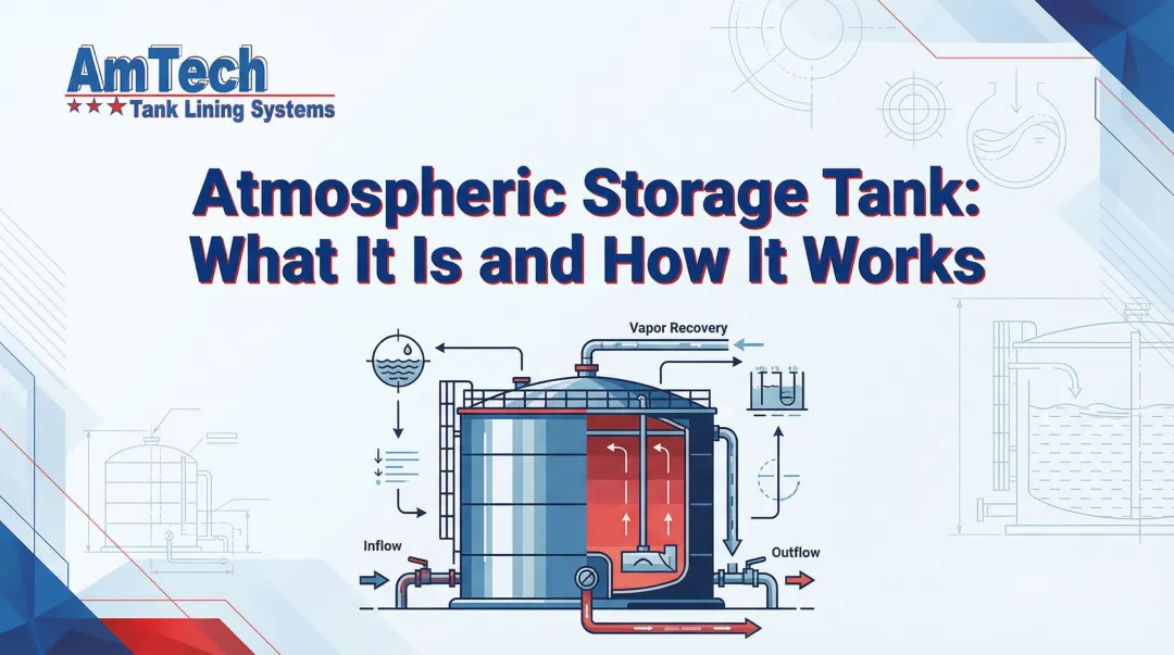
A tank described as "atmospheric" actually operates slightly above and below ambient pressure during normal breathing cycles—filling, emptying, and thermal expansion/contraction. Industry papers describe these vessels more accurately as "low-pressure" tanks, typically spanning a design pressure range of approximately +56 mbar to −26 mbar in standard configurations, with extended ranges possible depending on venting configuration.
Regulatory Baseline
OSHA 1910.106(a)(2) defines an atmospheric storage tank as one designed to operate from atmospheric pressure through 0.5 psig. API 650 frames the standard scope for near-atmospheric operation, while Annex F extends the upper limit to 18 kPa (2.5 psi) above atmospheric for elevated-pressure applications.
Design Parameter vs. Operating Variable
Design pressure is a design parameter set during the engineering phase based on the worst-case credible pressure scenario. It governs:
- Wall thickness and shell course calculations
- Roof-to-shell joint strength and weld specifications
- Venting system sizing and relief device selection
- Nozzle reinforcement requirements
It is not an operating variable that changes during service—it is a fixed structural limit established before fabrication begins.
Factors That Influence Design Pressure in Real-World Operation
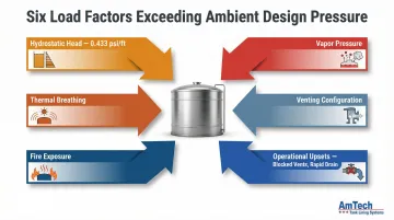
Several load inputs drive design pressure above a purely theoretical atmospheric value:
Hydrostatic and vapor loads factor in first:
- Hydrostatic head from stored liquid increases pressure with depth at approximately 0.433 psi per foot
- Vapor pressure of the stored product at maximum operating temperature
- Thermal breathing loads from ambient temperature swings and solar radiation
Venting configuration has an equally direct effect. An open vent tank with a frangible roof-to-shell joint operates at effectively atmospheric design pressure. The same tank fitted with a pressure/vacuum (PV) valve and no frangible joint must be designed to the emergency vent setting pressure plus pressure drop plus a safety margin — a substantially higher value.
Environmental and operational upsets round out the picture:
- External fire exposure (the primary emergency venting case)
- Rapid liquid inflow or outflow beyond normal vent capacity
- Blocked or frozen vent lines
- Over-filling or accidental valve isolation during draining
Vacuum events from rapid draining or sudden temperature drop are historically more destructive to thin-walled atmospheric tanks than overpressure events.
Design Pressure Range: Nominal Values, Vacuum Ratings, and Safety Margins
Design pressure for atmospheric tanks is not a single universal value but a range bounded by tank configuration, applicable code, and venting device selection.
Nominal Design Pressure Range
For API 650 tanks within the main standard scope, internal design pressure is effectively atmospheric—governed by a ±25.4 mm (1 inch) water column threshold below which no additional shell calculations are required. Under Annex F, internal design pressure may extend up to 18 kPa (approximately 2.5 psi).
OSHA's 0.5 psig upper bound sets the regulatory ceiling for the "atmospheric tank" classification.
These ranges hold under the following assumptions:
- Adequate venting is installed and sized correctly
- The roof-to-shell joint is designed per code requirements
- The stored liquid does not generate vapor pressures that push internal conditions above the vent set point
Upper and Lower Pressure Boundaries
Upper Boundary (Positive Pressure Limit):
The upper boundary is set by:
- Relief device opening pressure
- Pressure drop across the device at full flow
- Added safety margin
For a PVV-equipped tank with a frangible joint, internal design pressure is typically set at 200% of the PVV setting pressure. For a non-frangible configuration with an emergency vent, the designer must calculate:
Pd = Pa + ΔPv + S
Where:
- Pd = Internal design pressure
- Pa = Emergency vent setting pressure
- ΔPv = Pressure drop through emergency vent at full flow
- S = Safety margin
Vacuum Boundary (Negative Pressure Limit):
Atmospheric tanks are structurally very weak under vacuum. API 650 recognizes this vulnerability, and design vacuum pressure for PVV-equipped tanks is commonly set at 200% of the vacuum setting of the PVV. Tanks constructed from thin plate (as thin as 3–4 mm in smaller sizes) can be permanently distorted or destroyed by vacuum levels that would be negligible in a pressure vessel.
Safe Operating Margin
The design pressure must exceed the maximum operating pressure by a defined margin to accommodate:
- Unexpected pressure transients
- Measurement uncertainty
- Inherent limitations of relief device response time
Operating pressure for PVV-equipped tanks is commonly estimated at approximately 70% of the PVV setting pressure, providing headroom between normal operating conditions and the relief activation point.
Operating persistently near the design pressure boundary creates compounding structural risks:
- Accelerated fatigue in welded seams
- Roof-to-shell joint stress
- Potential loss of frangibility in designed weak-seam connections
All of these compromise the tank's last line of defense against catastrophic over-pressurization.
How Tank Configuration and Venting Drive the Design Pressure Calculation
Four principal API 650 design cases determine design pressure, based on two variables: the type of venting device installed and whether the roof-to-shell joint is designed to be frangible.
The table below shows how each case is configured before diving into the calculation requirements:
| Case | Vent Type | Frangible Joint | Emergency Vent Required |
|---|---|---|---|
| 1 | Open vent | Yes | No — frangible joint serves as relief |
| 2 | Open vent | No | Yes |
| 3 | PVV | Yes | No — frangible joint serves as relief |
| 4 | PVV | No | Yes |
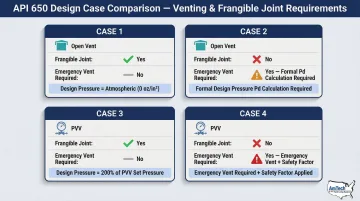
Case 1 – Open Vent with Frangible Roof-to-Shell Joint
Both operating pressure and internal design pressure are treated as atmospheric. The open vent must handle the full breathing load within ±25.4 mm (1 inch) water column pressure drop. Because the frangible joint acts as the emergency pressure relief mechanism, no separate emergency vent device is required — but the tank designer must calculate the joint failure pressure and confirm it falls within acceptable limits.
Case 2 – Open Vent Without Frangible Joint
Without a frangible joint, a dedicated emergency vent is required. The emergency vent setting pressure must exceed the normal vent pressure drop threshold to prevent cycling. This is the only open-vent case where a formal design pressure calculation applies:
Pd (internal design pressure) = Pa + ΔPv + S
Where:
- Pa = Emergency vent setting pressure
- ΔPv = Pressure drop through the emergency vent at full flow
- S = Safety margin
Cases 3 and 4 – PVV-Equipped Tanks
When a pressure/vacuum valve (PVV) replaces an open vent, operating pressure is estimated at 70% of the PVV setting pressure for both Case 3 and Case 4. Vacuum design pressure is set at 200% of the PVV's vacuum setting in both cases. The distinction between the two comes down to the roof joint:
With Frangible Joint (Case 3):
- Internal design pressure set at 200% of PVV setting pressure
- No emergency vent required — frangible joint provides relief
Without Frangible Joint (Case 4):
- Additional emergency vent is required
- Internal design pressure must exceed emergency vent pressure at 100% flow, plus a safety factor
How Design Pressure Is Specified, Measured, and Validated
Design pressure is established during the engineering phase and documented in the tank's design basis, datasheet, and engineering drawings. API 650 requires the purchaser to specify the design pressure; the fabricator then designs shell courses, roof plates, nozzle reinforcements, and the roof-to-shell joint accordingly. Code-calculated ratings and hydrostatic test pressures serve different purposes and are not interchangeable.
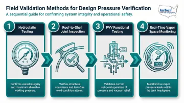
Field Verification Methods
Design pressure cannot be directly "measured" during normal operation the way flow or temperature can, but it is validated through:
- Hydrostatic testing during commissioning confirms structural integrity at design limits
- Roof-to-shell joint inspections catch early signs of distortion or weld fatigue
- Functional venting device tests verify PVV set-point accuracy and emergency vent lift-off response
- Pressure gauges and vacuum indicators monitor real-time vapor space pressure during operation
Laboratory Ratings vs. Field Performance
PVV manufacturers publish set-pressure and flow curves under standard conditions. However, field installations with long vent lines, flame arresters, or partially blocked screens introduce additional pressure drops that reduce effective relief capacity and can cause the actual tank vapor space pressure to exceed the device's labeled set point.
API 2000 guidance requires accounting for:
- Pressure losses through inlet piping and pipe penetrations
- Pressure drop across block valves upstream of venting devices
- Backpressure from common discharge headers
What Happens When a Tank Operates Outside Its Design Pressure Range
Overpressure Failure Mechanisms
Because roof plates and the roof-to-shell joint are the structural weak points, overpressure events first manifest as:
- Roof plate bulging
- Weld cracking at the roof-to-shell joint
- Controlled separation at the seam (in frangible joint designs)
When overpressure goes uncontrolled — from blocked vents, rapid vapor generation, or external fire — the consequences escalate well beyond localized joint failure:
- Projectile roof failure
- Full liquid release
- Fire or explosion (for flammable contents)
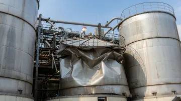
Vacuum Failure Mechanisms
Under-pressure damage is actually more common in atmospheric tanks than overpressure. Structural resistance to vacuum is extremely low, and several routine scenarios can generate it quickly.
Rapid draining without adequate inbreathing, vapor condensation during sudden cooling, or frozen vent lines can each produce vacuum sufficient to:
- Buckle thin shell courses
- Collapse the roof inward
- Permanently distort the tank structure
A 2006 paper published by the Institution of Chemical Engineers documented the destruction of a tank during decommissioning simply by removing a manway while draining faster than the vent could inbreathe.
Impact on Internal Coatings and Tank Integrity
When tanks experience repeated pressure excursions—even within technically allowable limits—the cyclic mechanical stress accelerates:
- Microcracking in internal linings and coatings
- Weakening of bonded surfaces
- Pathways for corrosive stored product to reach bare metal
After any documented over- or under-pressure event, lining inspection should be completed before returning the tank to service. This confirms liner integrity and catches microcracking or adhesion loss before corrosion takes hold.
Common Misconceptions About Atmospheric Tank Design Pressure
Treating Atmospheric Design Pressure as Equivalent to Zero or Ambient
"Atmospheric" describes the intended operating range relative to ambient, not the structural design limit. The tank must be engineered to handle pressure deviations above and below ambient — for example, vacuum relief settings typically range from −0.5 to −1.0 oz/in² (−0.22 to −0.43 kPa gauge). The design pressure is always a positive engineering value, never zero.
The Relief Valve Set Pressure Is Not the Design Pressure
The relief valve set pressure, operating pressure, and design pressure are three distinct values in the design hierarchy. Using the set pressure of a PVV as the tank's design pressure omits two required allowances: pressure drop through the device at full flow, and the safety margin above that. The result is an under-designed structure.
Applying a Single "Standard" Atmospheric Design Pressure Value Across All Tank Configurations
Some plant engineers default to quoting API 650's 2.5 psi (18 kPa) Annex F limit as if it is a universal design pressure for all atmospheric tanks. The actual design pressure depends on tank configuration:
- A tank with an open vent and frangible joint is designed to atmospheric pressure
- A tank with a PVV and no frangible joint carries a design pressure calculated case-by-case — often differing significantly from 2.5 psi
- A tank designed for both internal pressure and vacuum requires separate positive and negative design pressure values
Each configuration requires its own engineering evaluation. Defaulting to a single figure without reviewing vent arrangement, frangible joint status, and applicable code annex can result in either an over-built or non-compliant structure.
Conclusion
Design pressure in an atmospheric storage tank is a governing structural parameter—not a passive description—calculated from venting configuration, relief device characteristics, and applicable safety margins under API 650 and API 2000. It governs wall thickness, joint design, and the entire venting system.
Three factors must guide engineering judgment before finalizing any tank specification or repair scope:
- Vacuum vs. overpressure asymmetry — atmospheric tanks fail under vacuum at far lower differentials than they resist overpressure
- Operating pressure ≠ design pressure — design pressure includes safety margins the operating setpoint does not
- Calculation is case-specific — tank geometry, stored product, and venting configuration all change the result
Keeping a tank within its design pressure envelope over its service life requires correctly sized venting, regular inspection of structural welds, the roof-to-shell joint, and verified internal lining integrity. After any pressure excursion event, those elements need confirmation — not assumption.
With 55+ years of field experience in structural tank repair and lining, our crews inspect and restore that integrity directly, on-site, across all tank types and service environments.
Frequently Asked Questions
How do you determine the design pressure for an atmospheric storage tank?
Design pressure is determined by identifying the venting device type and configuration (open vent vs. PVV, frangible vs. non-frangible joint), calculating the relief device setting pressure and pressure drop at full flow, and applying a safety margin per API 650 case requirements and API 2000 venting calculations.
What design code applies to atmospheric storage tanks?
API 650 (Welded Tanks for Oil Storage) is the primary design standard for vertical cylindrical steel atmospheric tanks. API 2000 governs venting requirements, AWWA D100 applies to water storage tanks, and OSHA 1910.106 sets regulatory compliance requirements for tanks storing flammable liquids.
What is the design pressure for atmospheric storage tanks per API 650?
Under the main API 650 scope, design pressure is effectively atmospheric (±1 inch water column triggers no additional calculations). Annex F permits internal design pressures up to 18 kPa (approximately 2.5 psi gauge), depending on venting configuration and specific case requirements.
What is the pressure inside an atmospheric storage tank?
Normal operating pressure inside an atmospheric storage tank is very close to ambient atmospheric pressure but fluctuates slightly above and below due to breathing cycles (filling, emptying, and temperature changes). PVV-equipped tanks typically operate at approximately 70% of the relief valve setting pressure.
Is atmospheric pressure always 14.7 psi (1 atm)?
14.7 psia (101.325 kPa) is the standard sea-level reference value used in engineering calculations. Actual pressure varies with altitude, weather, and temperature. These variations are small but affect the differential pressure a tank's venting system must manage.
What is the vacuum rating for API 650 atmospheric tanks?
API 650 tanks equipped with pressure/vacuum relief valves are typically designed to a vacuum rating of 200% of the PVV vacuum setting pressure. Atmospheric tanks are structurally far more vulnerable to vacuum than to overpressure, so correct vacuum rating and inbreathing vent sizing are among the most critical aspects of the design.