Introduction
The floor of an above-ground storage tank (AST) is the most vulnerable surface in any storage facility. Exposed to corrosive stored product from above and soil-side moisture from below, tank bottoms face a dual-sided attack that no other structural component experiences.
Undetected corrosion in this zone has caused catastrophic failures, environmental spills costing millions in cleanup and fines, and unplanned shutdowns that ripple through entire operations across oil, gas, petrochemical, and water industries.
Consider the stakes: a 2015 jet fuel spill from an AST bottom at Sand Island resulted in a $150,000 EPA penalty, while the 2014 Elk River chemical spill in West Virginia—caused by a leaking AST—led to a $151 million class-action settlement. These aren't isolated incidents. The underlying problem is consistent: traditional inspection methods can't reliably detect the localized pitting and wall loss that precedes failure.
That's exactly what this guide addresses. You'll learn what corrosion mapping is, how the main inspection technologies work, how the process unfolds step by step, and what to do when corrosion is found.
Key Takeaways
- Corrosion mapping creates a detailed visual record of wall thickness loss and defect locations across tank bottom floors using systematic NDT methods
- Magnetic Flux Leakage (MFL) is the primary technology; ultrasonic testing (UT) and guided wave methods complement MFL for targeted follow-up
- The critical zone near the annular-to-shell junction weld is the highest-risk area and must be prioritized during inspection
- Inspection data drives repair, re-inspection, or protective lining decisions — without that step, the survey has no operational value
- API 653 and EEMUA 159 govern when and how tank bottom inspections must be conducted
What Is Corrosion Mapping and Why Does It Matter for Storage Tanks?
Corrosion mapping is a quantitative, non-destructive method of measuring and recording material wall thickness across an entire tank floor surface. The output is a spatial "map" showing where metal loss has occurred, how severe it is, and whether it originates from the product side (top) or soil/underside (bottom).
Why Tank Bottoms Are Uniquely Vulnerable
Tank bottoms face threats from multiple directions simultaneously:
- Product-side corrosion: Settled water bottoms containing corrosive salts, with microbiologically induced corrosion (MIC) driving localized rates as high as 1-2 mm/year
- Soil-side corrosion: Variable moisture conditions and galvanic activity, with average rates exceeding 10-15 mils per year at aggressive sites
- Mechanical stress: The annular-to-shell weld junction experiences concentrated stress that accelerates localized pitting
- Sludge accumulation: Creates oxygen-depleted zones that promote anaerobic corrosion

That combination means maximum pitting corrosion rates typically cause tank bottom holes and leaks — not generalized thinning across the floor.
The Regulatory Framework
API 653 governs in-service inspection of aboveground storage tanks and sets the inspection requirements operators must meet. It dictates:
- Inspection intervals calculated based on corrosion rate and remaining thickness
- Minimum remaining thickness requirements (typically 0.10 inches without leak detection, 0.05 inches with detection or reinforced linings)
- Fitness-for-service evaluation criteria that determine whether a tank can return to operation
Non-compliance means regulatory penalties and forced shutdowns. The EPA enforces the Oil Pollution Act and Clean Water Act, and operators bear direct liability for spills tied to inadequate floor integrity — a liability that survives even "we didn't know" arguments once an inspection was overdue.
Why Spot UT Isn't Enough
Traditional manual spot ultrasonic testing captures less than 1% of total tank floor area. Taking 5 spot measurements per floor plate leaves facilities highly vulnerable to undetected localized pitting. Comprehensive corrosion mapping provides systematic, documented coverage that gives inspectors — and regulators — a defensible record of floor condition across the full surface area.
Inspection Technologies Used for Tank Bottom Corrosion Mapping
No single technology solves every challenge in tank bottom inspection. Modern programs use a primary technology supplemented by complementary methods, with selection depending on tank size, floor plate thickness, coating condition, and required data detail.
Magnetic Flux Leakage (MFL) — The Industry Primary
A powerful magnet saturates the steel plate. Where metal loss exists, magnetic flux "leaks" out and sensors detect the field variations — generating signals that indicate defect location and relative severity. MFL has been the globally recognized primary method since Saunderson's foundational 1988 work. It remains the fastest option for comprehensive floor coverage.
Modern MFL systems have addressed many of the method's historical limitations:
- Critical zone coverage: Curved/angled attachments now reach the annular-to-shell weld area — previously considered a dead zone
- STARS technology: Surface Topology Air-Gap Reluctance System discriminates between top-side and bottom-side defects via magnetic field strength variations
- Paperless data acquisition: Onboard systems eliminate manual note errors and produce traceable C-scan imaging reports
- Acquisition speed: Modern scanners run at 500 mm/sec to 1 m/sec (19.7–39.4 in/sec)
- Through-coating capability: Effective through non-magnetic coatings up to 10 mm thick; thicker coatings reduce signal amplitude
Ultrasonic Testing (UT) and Phased Array UT (PAUT)
MFL flags defects across the full floor — but confirming what those signals mean requires a different tool. Spot UT provides less than 1% floor coverage on its own, making it ineffective as a primary method. Its role is confirmation: verifying and sizing indications flagged by MFL, establishing defect surface origin, and satisfying minimum UT scrub requirements in areas MFL can't physically reach.
Phased Array UT (PAUT) closes the gap between spot sampling and full coverage. It uses probes with multiple piezoelectric elements pulsed independently with computer-calculated time delays, enabling electronic beam steering and focusing without mechanical movement. The result:
- High-resolution mapping: 1–5 mm resolution vs. 25–250 mm for conventional spot UT
- Rapid coverage: Electronic beam sweeping replaces slow mechanical rastering
- Superior characterization: Detailed depth, length, and morphology data for complex pitting
- Targeted coverage: 100% of scanned zones vs. <1% statistical sampling
For encoded scans across suspected corrosion areas, dual element linear array (DLA) probes with magnetic wheel encoders deliver detailed C-scan imaging of defect morphology.
Guided Wave and Emerging Methods
When a tank can't be taken out of service, magnetostrictive transducer (MsT) arrays offer a screening alternative. Sensors coupled to the tank's chime (skirt) from outside generate ultrasonic guided waves in the 20–150 kHz range, screening for defects without requiring entry or emptying — cutting confined space exposure and mobilization costs.
The method has real constraints to account for:
- Blind zones typically 11–20 cm behind the vertical wall where coverage is lost
- Dead zones near the probe itself
- Degraded performance on heavily corroded surfaces or complex geometries
- Mode conversion at welds can generate false signals that complicate interpretation
Guided wave is best treated as a between-inspection screening tool. When it flags areas of concern, those findings still require internal inspection to confirm severity and plan repairs.
How Corrosion Mapping Works: Step-by-Step
Corrosion mapping is a multi-phase process that begins well before any scanner enters the tank and continues after the last data point is collected. Skipping steps at any phase — from preparation through reporting — directly undermines the reliability of maintenance decisions and API 653 fitness-for-service assessments.
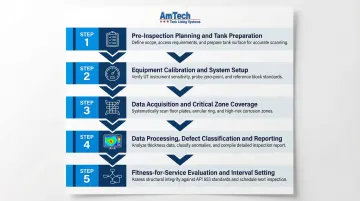
Step 1 – Pre-Inspection Planning and Tank Preparation
- Tank must be taken out of service, drained, and degassed (where applicable)
- Cleaned to remove sludge, scale, and debris that interfere with MFL signal quality (inadequate cleaning is the most common reason inspection data degrades)
- Review previous inspection records to establish baseline corrosion rates
- Identify plate thicknesses (annular vs. inner plates often differ)
- Confirm applicable standards (API 653, EEMUA 159)
- Define coverage zones with specific critical zone protocol
Step 2 – Equipment Calibration and System Setup
MFL equipment must be calibrated to the specific plate thickness being inspected — a mismatch between calibration and actual plate thickness is one of the most common sources of inspection data error:
- Thicker inspection surface than calibration plate: System becomes under-sensitive, undersizing defects
- Thinner inspection surface: System becomes oversensitive, increasing spurious defects and oversizing flaws
- Coatings thicker than 0.5 mm (20 mils): Must be simulated during calibration using non-magnetic shims
Modern systems include software safeguards preventing data acquisition if calibration parameters don't match current plate thickness. Calibration records must be included in final reports to support data integrity.
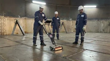
Step 3 – Data Acquisition and Critical Zone Coverage
The MFL scanner is driven systematically across the tank floor in overlapping passes, recording position-tagged data continuously. Primary coverage of the main floor is supplemented by critical zone protocols — curved scanning attachments or secondary UT scrubbing ensure annular plates and shell junction areas receive adequate coverage.
Scanning speed directly affects signal quality. Modern scanners are rated at maximum speeds (typically 0.5 to 1 m/sec), and operators must hold within that range to avoid degraded data.
Step 4 – Data Processing, Defect Classification, and Reporting
Raw MFL data is processed into C-scan corrosion maps that display the entire floor with color-coded severity indicators. Defects are classified by:
- Estimated wall loss percentage
- Surface origin (top vs. bottom)
- Location coordinates
UT measurements are then taken at flagged indications to verify and size the most significant defects (the prove-up stage).
A complete inspection report must include:
- Coverage statistics
- Calibration records
- Prove-up location data
- Defect severity maps
- Clear indication lists
This package gives asset owners a defensible, auditable record for API 653 fitness-for-service decisions and regulatory compliance.
Step 5 – Fitness-for-Service Evaluation and Inspection Interval Setting
Under API 653, minimum allowable remaining thickness is calculated based on tank design, operating pressure, and product stored:
MRT = (Minimum of RTbc or RTip) - Or × (StPr + UPr)
Where:
- Or = in-service interval
- StPr = maximum rate of un-repaired top-side corrosion
- UPr = maximum rate of bottom-side corrosion
Two outcomes follow from the assessment:
- Remaining thickness meets minimum: Tank returns to service with a calculated next inspection interval
- Below threshold: Tank must be repaired before returning to service
Corrosion rate data from the inspection projects when a tank will reach minimum thickness — the key input for scheduling future inspections. Remaining life = (tactual - tminimum) / corrosion rate.
From Inspection to Repair: What to Do After Corrosion Is Found
A corrosion map is only as valuable as the action it drives. Asset owners face a decision tree after receiving inspection results:
Decision Framework
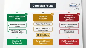
Minor, Localized Pitting: Can be monitored with shortened inspection intervals if remaining thickness exceeds minimum requirements by adequate margin.
Moderate Wall Loss: Requires localized plate repairs or repair patches. API 653 Section 9.10 governs repair methods:
- Welded-on patch plates permitted for uniformly supported bottoms
- Minimum dimension requirements (12 inches if overlapping a seam)
- Critical zone patches must be tombstone-shaped and intersect shell-to-bottom joint at 90 degrees
Severe or Widespread Corrosion: Requires full bottom replacement or re-lining. API 653 outlines procedures for complete bottom replacement, requiring noncorrosive cushion (sand, gravel, concrete) between old and new bottoms.
Common Repair Approaches
Depending on the extent of damage, three primary repair paths apply:
- Repair plates — Welded inserts replace discrete corroded sections and must meet API 653 dimensional and positioning requirements.
- Full floor replacement — Used when damage is too widespread for patch repairs to be practical or economical.
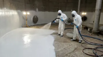
- Protective lining — Applied over repaired surfaces to prevent future corrosion and extend service life.
The Role of Protective Tank Lining
Repair restores structural integrity, but without a protective barrier, the same corrosive conditions will attack the steel again. A lining system—whether cementitious, epoxy, or high-solids polymer-based—isolates the steel floor from both the stored product and the soil-side environment, extending the interval between re-inspections from years to decades.
The right technology depends on the product stored, operating temperature, and regulatory requirements:
| Feature | 100% Solids Polyurea/Polyurethane | Cementitious Systems |
|---|---|---|
| Elongation | 40%+ (vs. 3-4% for epoxy) | Rigid; suited for stable surfaces |
| Thermal resistance | Withstands flexing and expansion | Up to 900°F |
| Cure time | Seconds to minutes | Standard cure schedule |
| Best for | Chemical, fuel, and petroleum tanks | Potable water and hot water tanks |
| Regulatory compliance | Excellent chemical resistance | NSF/ANSI 61 compliant |
| Service life | 10–20+ years | 40-year field history |
Regulatory Certifications:
- NSF/ANSI/CAN 61: For potable water (minimum health-effects criteria for chemical contaminants)
- UL 142: Steel Aboveground Tanks
- UL 2085: Protected Aboveground Tanks
Post-Repair Inspection
After repairs and lining application, conduct:
- Holiday (spark) test to verify coating integrity
- Baseline thickness readings to establish new corrosion map baseline
- Documentation for future comparison
With documented baseline readings in place, the next scheduled inspection has a clear reference point — and your integrity management program stays ahead of the corrosion cycle rather than reacting to it.
How AmTech Tank Lining & Repair Can Help
When corrosion mapping results require action, asset owners need a partner who can move from inspection findings to a restored, compliant, and protected tank bottom without delay.
55+ Years of Proven Expertise
AmTech brings engineer-trained crews, API-compliant processes, and a track record of restoring tank bottoms and extending service life by decades. Operating since the late 1960s, the company has repaired and relined thousands of steel, concrete, fiberglass, and FRP tanks.
Industries served include oil and gas, petrochemical, water and wastewater, and chemical processing—across all 50 states, Canada, and the Caribbean.
Proprietary Lining Systems
DuraChem® 500 Series 100% Solids Poly Lining:
- Instant cure on contact (minutes, not days)
- 80-125 mil film thickness in single application
- Adhesion strength up to 1,965 PSI
- Zero VOCs during application
- Flex and elongation characteristics that accommodate thermal expansion and tank movement
- Chemical resistance to acids, alkalis, petroleum products, and corrosive liquids
- ANSI, NSF, NLPA, API, and UL compliant
HydraStone Alkrete® Cementitious Lining: AmTech is the exclusive U.S. licensee of this proprietary calcium aluminate cement system:
- NSF/ANSI 61 compliant for potable water
- Temperature resistance to 900°F
- 40-year service history
- Minimum 5/8" thickness application
- Ideal for hot and cold water storage
Minimizing Downtime and Capital Expenditure
- Responds 24/7 for emergency service across North America
- Deploys in-house field crews only — no subcontractors, no handoffs
- Returns tanks to service same day or next day using DuraChem lining systems
- Backs all work with the Blue Check warranty program, covering labor and materials
Comprehensive Service Scope
AmTech's tank bottom repair services include:
- In-house ultrasonic testing and NDT inspection
- API 653-compliant structural steel repairs
- Surface preparation (abrasive blasting, hydroblasting)
- Floor pan installation (FRP or polylining)
- Post-repair verification testing
- Full documentation for asset owner records
For a free project evaluation following your corrosion mapping findings, contact AmTech at 888-839-0373 or visit www.amtechtanklining.com.
Frequently Asked Questions
How often should storage tank bottoms be inspected for corrosion?
API 653 sets inspection intervals based on the tank's corrosion rate, remaining thickness, and projected date of minimum allowable thickness. Intervals typically range from 5 to 20 years, with risk-based approaches under API 580/581 allowing adjustments for leak detection availability, construction materials, and corrosion mitigation methods.
What is the difference between MFL and ultrasonic testing for tank bottom corrosion mapping?
MFL is the primary scanning technology offering rapid, comprehensive floor coverage and high probability of detection across entire tank floors. UT is used as a prove-up and sizing method to verify specific indications flagged by MFL, confirm defect depth, and determine surface origin. The two methods are complementary, not competing, in a complete inspection program.
What is the "critical zone" in storage tank corrosion mapping?
The critical zone is the area of the tank floor near the annular-to-shell junction weld—a high-stress, high-risk region where corrosion damage is most likely to cause structural failure. This zone requires specialized curved-scanning MFL equipment or manual UT scrubbing to inspect adequately, as standard MFL scanners cannot reach this area due to geometric constraints.
Can corrosion mapping be done without taking the tank out of service?
Traditional internal MFL and UT corrosion mapping requires the tank to be emptied, cleaned, and entered. Emerging exterior guided wave methods can perform screening-level inspection without decommissioning, but these remain supplementary tools with limitations including blind zones and reduced detection sensitivity, and do not replace internal inspection.
What repairs are typically required after corrosion is found in a tank bottom?
Repair scope depends on severity: localized pitting may require spot repair plates or weld deposits, while widespread wall loss may require partial or full floor plate replacement — all per API 653. Repairs are typically followed by a protective lining system (polyurea, polyurethane, or cementitious) to prevent future corrosion and restore the floor to compliant service.
Does applying a protective tank lining eliminate the need for future corrosion mapping?
No. A quality lining system significantly slows corrosion rates and extends inspection intervals, but API 653 still mandates periodic inspection. Linings can degrade or disbond over time, so inspections remain necessary to confirm lining integrity and detect corrosion beneath the coating.